I just acquired two interesting pieces of hardware for review. The first is an XMOS USB Audio reference design board ($150 from Digikey) and a new USB Oscilloscope called the QuantAsylum QA100 ($350 from the QuantAsylum website). The XMOS board provides ADC and DAC running at 192 Ksps and delivering 24-bit performance. The oscilloscope delivers 100Msps and has 12 digital channels to go along with its two analog channels. I have some ideas for the 24-bit ADC and DAC that will eventually tie into both RC and CNC. These aren’t yet baked, but hopefully will be soon.
The XMOS offering is very interesting because it puts unbelievable ADC resolution and bandwidth in our toolkit, and allows access to this precision using standard Win32 audio APIs. Think about this: If you assume 1Vpp is full scale, then a 24-bit converter can resolve measurements to around 100 nV. Without scaling. Without an FPGA. And without complicated USB drivers. Of course, real world will limit your actual resolution. That is part of my goal with getting this board: to understand and quantify this.
The scope is very interesting because it offers a features at a price that hasn’t previously been matched, anyplace. I know, some like to pooh-pooh USB scopes, especially since the Rigol has gained so much traction. But I’ve come to the opinion that those that use a Rigol aren’t really doing anything that demanding except measuring clocks and siggen outputs. The Rigol software to get waveforms to your PC is wanting. And forget trying to decode the logic signals. Now, compared to the Rigol’s 1 GSps sampling rate, the the 100 Msps might seem slow. And if you are working on a 100 MHz ARM processor it is definitely a slow. But if you are on a 16 MHz MSP430 or AVR, it’s plenty. And did I mention the protocol decoding?
Sitting around the QA100 scope in terms of price you have (from Gabotronics’ excellent list):
- PropScope from Parallax for $199 is dual channel with 4 digital inputs, but a 25Msps sampling rate. With this sampling rate it’d be tough to debug even most AVR/PIC/MSP processors. But if funds are tight, this is certainly better than nothing.
- Link Instruments MSO19 is $239, with a single 8-bit ADC running at a healthy 200 MHz, and it also has 8-bit logic analyzer. But the buffer depth is woefully small and the scope noise and resolution is very limiting.
- Virtins DSO2810F for $250 is a 2 channel scope with 8-bit ADC, but the buffer is very small and it lacks a logic analyzer
- Virtins DSO2815 for $350. It’s 2 channel, with just 8-bit ADC. It does have 150Msps, but it lacks a logic analyzer.
- Veleman PCSU1000 is $360. It’s also 2 channel with 8-bit ADC, but only 50Msps. It also lacks a logic analyzer.
-
Bitscope BS50U is $475, and it does have a logic analyzer, but only a single 8-bit input, and only 40Msps sampling rate.
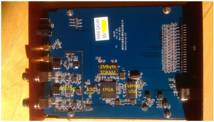
One other unique feature about the QA100 is the deep buffer. The website claims 1MByte, the scope has 2Mbyte written on the case. But the software only allows access to 1Mbyte. In any case, big buffers are your friend if you are every trying to figure out a complicated problem and your triggering options are limited.I opened the scope and looked inside,
The Scope Case and Guts
Plastic cases seem to be the norm for USB scopes. The fit well in a backpack, but forget stacking them. The QA100 resembles a tiny piece of stereo equipment. Your first thought when you pick up the cold steel case is “man, this thing is light.” The QuantAsylum team in China has indicated they will build a family of products that can stack on top of each other to conserve desk space. And like racks of pro-audio sound gear, the concept is definitely valid. However, since things like logic analyzer functions usually require the box to be next to the hardware being debugged, it’s reasonable to guess that much of the time the box will be removed from whatever rack they come up with.
Inside the scope there’s not too much. An analog front end with parts from ADI, an ADC, FGPA, memory and the USB part. As is the norm with most products from China, the part numbers are scratched off.
Scope Power and Operation
The scope is powered via USB. This is no surprise, as USB can deliver up to 2.5W. And the scope specs do claim that all 500 mA of this is needed. So you will either need a powered hub, or a dedicated port on your PC to run this thing. It doesn’t get hot or even warm. It has large cooling holes on the side, but even if those were plugged up I don’t think this would get hot. Firing up the scope for the first time is as simple as 1) install the software, and 2) plug in the scope. Those on Vista and later get the benefits of all automated driver installation. Those still on XP get to do the USB install old-skool. But by now it should be old hat.
The scope comes with two 100 MHz probes, which is a bit surprising considering the 25 MHz bandwidth of the scope. They are vanilla probes. Nothing too special. They do come with a small pouch of accessories.
The UI
The UI is easy to use. Where a normal scope has a knob, this scope also has a knob, albeit virtual. If you haven’t yet bought a mouse with a scroll wheel, then this is hopefully the excuse you are looking for to justify the $8 scrolling mouse to your spouse. To change a setting, you just roll over the knob, and then use the scroll wheel to adjust the setting up or down. Feedback is immediate. The entire left side of the screen is a panel that is initially always present when you first run the app. You can unpin that at the top, and then when you roll out of the knob and button area, the controls tuck neatly away.
First Capture
The XMOS board requires USB audio drivers to be installed, because standard Windows USB drivers cannot do HD (although Apple can apparently drive this board right out of the box without any driver install). But the install went off without a hitch although it took a long time.
I wrote a quick app in C# using the excellent NAudio library. This allows us to kick off audio recording with the ridiculously simple 5 lines of code:
private void button1_Click(object sender, EventArgs e){WaveIn = new WaveIn();WaveIn.WaveFormat = new WaveFormat(192000, 24, 1);WaveIn.DataAvailable += new EventHandler<WaveInEventArgs>(waveIn_DataAvailable);WaveIn.RecordingStopped += new EventHandler(waveIn_RecordingStopped);//Writer = new WaveFileWriter(@"c:\trash\audiofile.wav", WaveIn.WaveFormat);WaveIn.StartRecording();}
With the above code kicking off the 192Ksps sampling engine, we can look at some signals. A quick review of I2S. The protocol consists of a stream of data running to the DAC, a stream of data running from the ADC, a LRCLK which indicates if the left or right audio audio channel is currently being sent or received, and a master clock which is used to clock in each individual bit of audio data. If each channel is 32-bit data, then the that means it will take 32-bits to clock in the left channel, and 32-bits to clock in the right channel. At 192 KHz sample rate, 32-bits per channel and two channels, the bit clock will be 12.29 MHz.
After soldering on a 7 pin header and a ground pin (holes already exist for each on the USB board), I connected the scope to the pins using the color coded logic analyzer lines. The colors follow the resistor color code, so it’s easy to grab a handful of wires and sort them out at the connector without needed any printed help to figure out what goes where. Assigning the names to each is handled quickly in a Settings menu. With that done, I started the test app, pressed run on the oscilloscope, quickly added a rising edge trigger on the LRCLK just by clicking to the right of the label. This was NOT clear to figure out, and required a visit to the help manual. A friendly prompt told me the trigger I had just set was disabled and to enable the logic trigger on the panel button. Makes sense, and I liked the prompt.
Still wondering about the benefit of a USB scope compared to a bench top? Consider the Rigol is 320 x 254 resolution. A Nintendo DS handheld gaming device has a resolution of 256×192. That’s right, the Rigol has slightly better resolution than a Gameboy. A USB scope captures at your desktop resolution. The capture below is almost 1050 pix wide. That yellow box below is the number of pixels a Rigol can show you. Now is it starting to make sense?

Making measurements is done by pressing the key ‘1’ to get the #1 cursor, and ‘2’ to get the #2 cursor (also not obvious, but explained in the short cut section of the manual). Once your cursors are displayed, you can drag them wherever you wish with the mouse. Snap would have been nice, but it’s not too difficult to get things lined up. Here we are at a 100Msps sample rate, and we can see the LRCLK has a frequency of 192 KHz. We can also see activity on the ADC Data line. The MCLK is hard to see at this resolution, so we zoom in:

If we count 10 cycles with the cursors, we can see this is about 2.38 MHz, or 23.8 MHz per cycle averaged over 10 cycles. The averaging is needed because this clock frequency is getting close to our sample frequency. This is 64 bits shifting in on the left channel, and 64 bits shifted in on the right channel (192KHz * 64 * 2= 24.58 MHz). I expected 32 bits on the left, and 32 bits on the right, so I’m a bit surprised here. But it’s definitely showing the limits of the scopes digital capture capabilities.
By the way, I had both the XMOS board and the Scope connected to the same hub and the XMOS board was reporting 20.2 screen updates per second. If you have ever used a USB scope before, that is very fast for having so many channels displayed.

Analog Capture and Playback
The codec on the XMOS board is a Cirrus CS4270, which is reasonably integrated and offers a noise floor around -95 dB. This is actually fairly poor compared to other high rate codecs out there. But it’s reasonable. However, this means we can only resolve uV instead of the alluring nV that the 24-bit width would imply. Still pretty good.

I was unable to get playback working at the advertised bitrate of the XMOS USB 192 KHz. So, I fell back to the 44.1 KHz to make some noise measurements. In the capture below, I set the trigger to capture the “ping” test noise that Windows plays when you are setting up your speakers. Here you can see the trigger is set to roughly about 5 mV and we’re AC coupled. Now, this is where an interesting feature of the scope comes into play. Digital scopes usually focus on sweep time instead of sample rate. While that made sense when engineers were still transitioning from analog to digital 20 years ago, today most engineers think in terms of sample rate all the time. The QA100 always shows the sample rate just under the sweep time, and it also provides a “resolution” knob that lets you bump it up or down as you see fit. Here, for a 5 mSec/div sweep the scope decided a 10 Ksps was needed, but over-rode that setting with a whirl of the mouse wheel and increased it 5X to 50 KSPS. This causes the amount of signal I could see to drop, but a turn of the depth knob brought that back. As you can see in the lower right, there are 2048 samples being collected, and the total acquisition time is 40.96 mSec. This also tells me my theoretical update rate at these settings is about 24 frames per second (1/41 mS).
With these settings, you are able to see the low noise performance of the scope. This is one area where USB scopes have historically deserved a bad name. Early USB scopes for hobbyists, such as the Link Instruments MSO19 and Parallax scopes, really did have unusable low noise performance. Anything below 100 mV or so and you couldn’t tell the signal from the noise. But below the signal is measured at 31.5 mVpp (from M3 to M4 on the left side of the screen) and the noise is very reasonable here.
The digital portion is a mess at this sample rate, as there are just too many transitions to show. But the software does a good job of coping with so much redundant information on the screen. In fact, even with buffer depths at the maximum depth the software was still reasonably responsive while scrolling.

The scope has a 10-bit ADC, which limits the noise floor of the scope. But with the spectrum analyzer function, we can at least get an idea of what is happening. Consider the Windows “bing” test tone again. Here we see it in the time domain, where it appears the fundamental frequency is about 829 Hz:

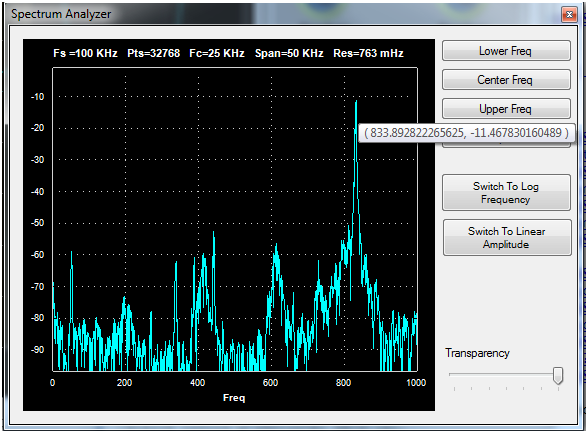
And here we see that same signal in the frequency domain. The peak at -12 dB is measured as 833 Hz. Note the resolution at this buffer depth (65536 samples) is 763 milli-Hertz.

Unfortunately, the software doesn’t have the ability to show markers. But you can set the upper and lower freq limits, and then see values by hovering over peaks. Below we see the peak is 833 Hz, and -11.46 dBFS. And again, we get stunning frequency resolution thanks to the deep buffers. In fact, if we used the full 1Mbyte buffer here, the resolution would be closer to 1/10th of a Hertz.
Summary
Overall, I look forward to both of these being in the toolbox. The USB board is a good price. The driver isn’t quite doing what I expect in all situations with the NAudio library, but I suspect will be able to work through that. The scope offers a new features at a price that hasn’t yet been achieved by existing equipment.

[…] the last post I looked at the overall PCB of the QA100. In this post I wanted to look more at the individual parts. Recall the main PCB […]
Pingback by QuantAsylum QA100 Oscilloscope Teardown « engineeringtopics — September 24, 2011 @ 11:09 pm